Gas Turbine Generator Technical Information:
Turbine: Westinghouse 1 X W251B11/12 ECONOPAC, Configuration: Gas Turbine,
simple cycle. Capacity: 1X48 MW ISO
Type of fuel (start): No. 1 distillate Type of fuel
(operation): Diesel with option to convert to natural gas
Water injection included Turbine: Synchronous direct coupling
Compressor: 19-stages axial flow Turbine: 3 stages
Speed: 5,418 rpm Speed Reduction 3,000 rpm
Generator: synchronous 3-phase, air cooled,
66.65 MVA, 11.5 kv, 50 Hz Output: 11.5 kv - 50
Hz GSU rating 33 KV
Operating hours - 29,894 Starts 804
Description of the Power Generation Plant
The ECONOPAC developed by Westinghouse was designed to provide a complete
generation system. All components and subsystems were carefully selected and
optimized to form a compact plant; the barge and its elements are designed to
comply environmental requirements.
The ECONOPAC features modular construction to facilitate shipment and assembly.
The system was pre-assembled to the maximum extent permitted by shipping
limitations. Where possible, subsystems were grouped and installed in auxiliary
packages to minimize field assembly. These packages were completely assembled
and wired at the factory and require only interconnection at the
site. Pipe rack assemblies were supplied eliminating the need for
extensive piping fabrication during construction.
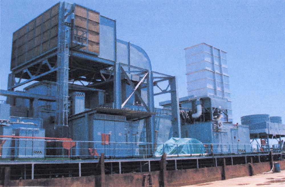
Recognized as the heart of the ECONOPAC plant, the prime mover consists of
three basic elements: the axial flow compressor, a combustion system and power
turbine. These three elements are combined into single assemblies that were
shipped complete with rotor in place, facilitating erection in the field.
Incorporated into the design are such features as a horizontally split casing,
tow-bearing support, turbine air cooling system, compensating alignment system.
The generator and the brushless exciter are equipped with integral lube oil
piping and necessary instrumentation. A solid coupling connects the generator
directly to the compressor (the cold end of the combustion turbine). The
electric motor starting package is a self-contained assembly, pre-mounted
on a bedplate and shipped as a complete module. The package contains all the
equipment necessary to provide breakaway torque for initial rotation of the
turbine generator, torque necessary for acceleration to self-sustaining speed
and a disconnect means to allow disengagement of the starting device once the
unit reaches self-sustaining speed. During the cool-down periods, the turning
gear automatically engages to provide for a slow roll of the combined turbine
and generator.
A side inlet air duct directs flow into the compressor inlet manifold. The
manifold was designed to provide an efficient flow pattern of the air into the
axial flow compressor. A parallel baffle-silencing configuration is located in
the inlet system for sound attenuation. A two-stage pad filter provides air
filtration. After expanding through the combustion turbine, the
gases pass though the exhaust manifold and exhaust transition. The exhaust gases
enter the atmosphere through the exhaust stack.
All control, protection and monitoring functions for the combustion turbine and
ECONOPAC systems are performed by the Powerlogic II control system. The core of
the system is the distributed processing unit (DPU) which perform all of the
control and logic functions. The input/output signal cards provide the interface
to the field instrumentation and control devices. A personal computer is mounted
in the local panel in the electrical package and serves as the man-machine
interface device for the system. This is both the systems programming device as
well as the operator interface. All control and monitoring functions can be
performed from this panel. A set of standard graphic displays is provided for
all
operational and monitoring functions. The PC also performs the logging
function. Standard sets of logs are provided for documenting combustion
turbine operational performance.
The local panel also houses other control related equipment such as the
vibration monitoring system, electromechanical counters and timers, trip
push-button, flame scanner electronics and other ancillary equipment.
The DPU and the operator interface and interconnected on the WDPF (Westinghouse
Distributed Processing Family) Westnet II data highway system. This is a high
level, high speed communication network that allows all WDPF devices to
communicate with each other and share a global information database. The data
highway interface to the PC is what enables the PC to be a high level fully
functional man-machine interface device for the system.
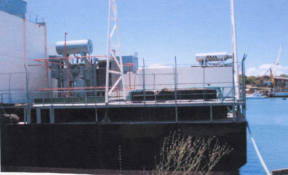
General Description of the Power Barge
All power generation equipment and other equipment are mounted on the hull.
The barge is intended to be moored at the site and remain in a
"floating" condition.
The hull was designed in accordance with the applicable portions of the current
American Bureau of Shipping (ABS) Rules for building and classing "Steel
Vessel", "Steel Vessels for Service on Rivers and Inter coastal
Waterway" and "Steel Barges". The barge was designed to be
"dry-towed", expect for coastwise voyages of limited duration and
exposure.
All materials were in accordance with ABS requirements for "ordinary
strength steel", Grade A or B, as applicable to thickness and location. All
welding procedures and materials were in accordance with ABS requirements.
The protection against corrosion and internal coatings were applied to maintain
the life span of the barge.
The bed frames, the foundations and support structures are designed for the
following conditions:
Operating under a storm: Equipment dead and live operational loads plus operation storm environmental loads.
Survival under a storm: Equipment dead loads plus survival storm environmental loads. A 1/3 increase in working
stress allowance was used for these design conditions.
Transportation: Equipment dead loads accelerations due to dry-tow transportation of the barge from the Shipyard to the operation site. A 1/3 increase in working stress allowance were used for these design conditions.
Power Train Loads: These loads were developed from the operational criteria set out by Westinghouse. The assumed environmental parameters used for the design of the barge and foundations are as follows:
Operating Storm: an operating storm is defined as the limiting site conditions in which the barge will remain operational.
Wind speed: 130 kph
Wave and current: none
Relative humidity: 60% - 100%
Ambient temperature: 38 C
Survival Storm: a survival storm is defined as the limiting site conditions in which the barge / foundations will survive without damage to their structure. Wind speed: 185 kph Wave and current: none.
In addition to the above, the barge and equipment foundations were designed to
survive sea states which produce 0.55g swat in combination with 0.20g heave
forces.
 |
|